thanhan1310
Intern
Cấu Hình Định Tuyến Tĩnh, VLAN Routing (Static Route)
- Tiếp tục với bài viết Lý Thuyết về Định Tuyến Tĩnh, VLAN Routing (Static Route)- Bài viết này mình sẽ hướng dẫn các bạn cấu hình Định Tuyến Tĩnh, VLAN Routing (Static Route) trên thiết bị Switch, Router Juniper
1. Định tuyến tĩnh (Static Route)
Sơ đồ mô hình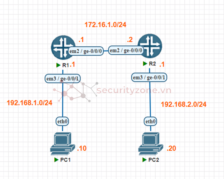
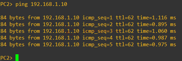
Mục tiêu : để 2 PC1 và PC2 có thể ping được với nhau
Đầu tiên ta gán địa chỉ IP cho PC1 và PC2 (gán cả IP default-gateway)


Tiếp theo đó ta cấu hình Router 1
Với interface em3 ta gán địa chỉ 192.168.1.1

Với interface em2 ta gán địa chỉ 172.16.1.1

Kiểm tra thử 2 interface đã được gán IP chưa

Tiếp theo đó ta định tuyến tĩnh để Router 1 có thể kết nối tới vùng mạng chứa PC2

Kiểm tra route bằng lệnh show route
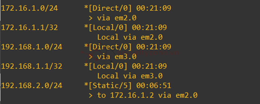
Ta có thể thấy Router 1 đã có thể kết nối vùng mạng 192.168.2.0 thông qua Router 2
Làm tương tự với Router 2


Kiểm tra route trên Router 2
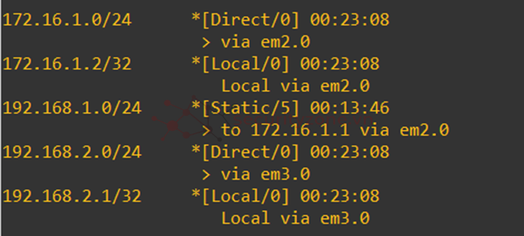
Cuối cùng là kiểm tra 2 PC ping nhau

2. VLAN Routing
2.1. Router-on-a-stick
Sơ đồ mô hình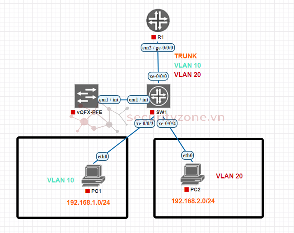
Đầu tiên ta cấu hình SW
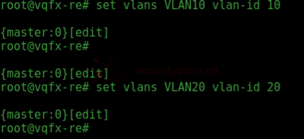
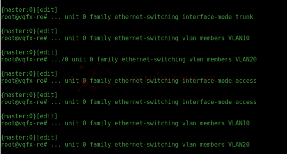
Ta tạo VLAN, add interface vào trong VLAN vừa tạo và setup interface thành mode trunk và mode access tương ứng cho mỗi interface :
set vlans VLAN10 vlan-id 10
set vlans VLAN20 vlan-id 20
set interfaces xe-0/0/0 unit 0 family ethernet-switching interface-mode trunk
set interfaces xe-0/0/0 unit 0 family ethernet-switching vlan member VLAN10
set interfaces xe-0/0/0 unit 0 family ethernet-switching vlan member VLAN20
set interfaces xe-0/0/1 unit 0 family ethernet-switching interface-mode access
set interfaces xe-0/0/2 unit 0 family ethernet-switching interface-mode access
set interfaces xe-0/0/1 unit 0 family ethernet-switching vlan members VLAN10
set interfaces xe-0/0/2 unit 0 family ethernet-switching vlan members VLAN20
Tiếp theo ta cấu hình Router
Đầu tiên ta bật chế độ vlan-tagging cho interface kết nối với Switch (ở đây là interface ge-0/0/0)
set interfaces ge-0/0/0 vlan-tagging

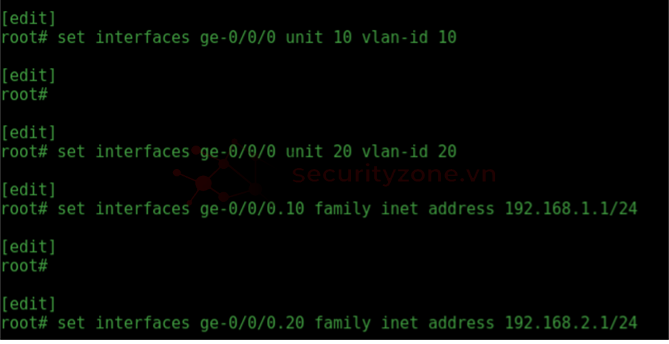
Tiếp theo đó ta cấu hình vlan-id tương ứng cho sub-interface ge-0/0/0, gán địa chỉ ip cho từng sub-interface tương tứng
set interfaces ge-0/0/0 unit 10 vlan-id 10
set interfaces ge-0/0/0 unit 20 vlan-id 20
set interfaces ge-0/0/0.10 family inet address 192.168.1.1/24
set interfaces ge-0/0/0.20 family inet address 192.168.2.1/24
Để có thể ping được thì ta phải set quyền cho sub-interface được gán địa chỉ ip
set security zones security-zone trust interfaces ge-0/0/0.10 host-inbound-traffic system-services ping
set security zones security-zone trust interfaces ge-0/0/0.20 host-inbound-traffic system-services ping

Kiểm tra kết quả sau khi cấu hình :
SW
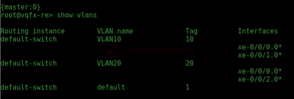
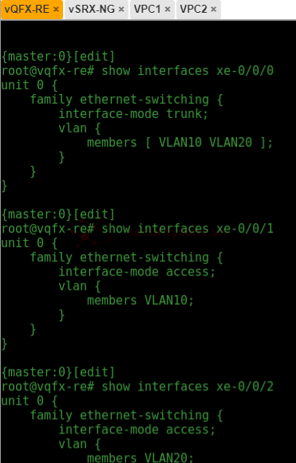
Router
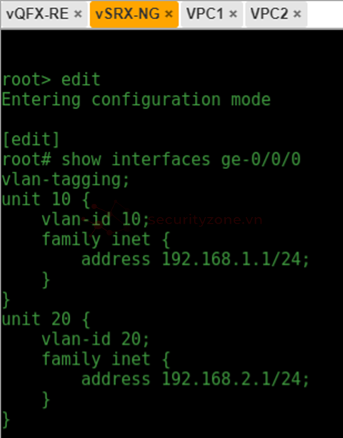
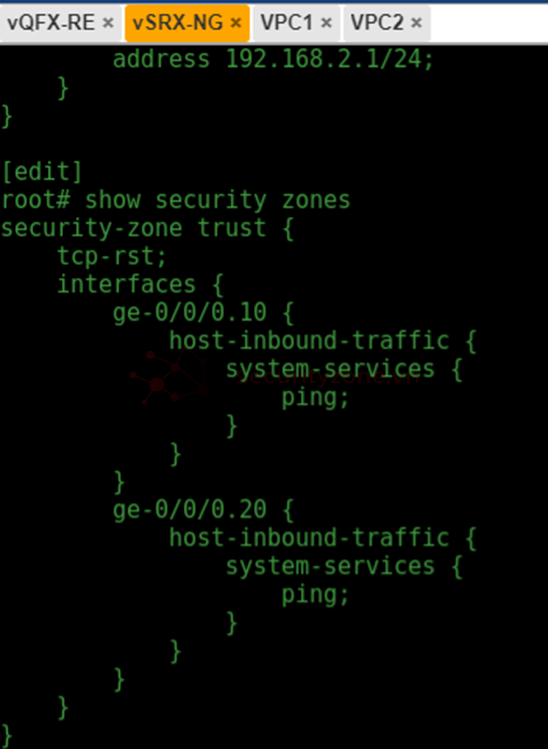
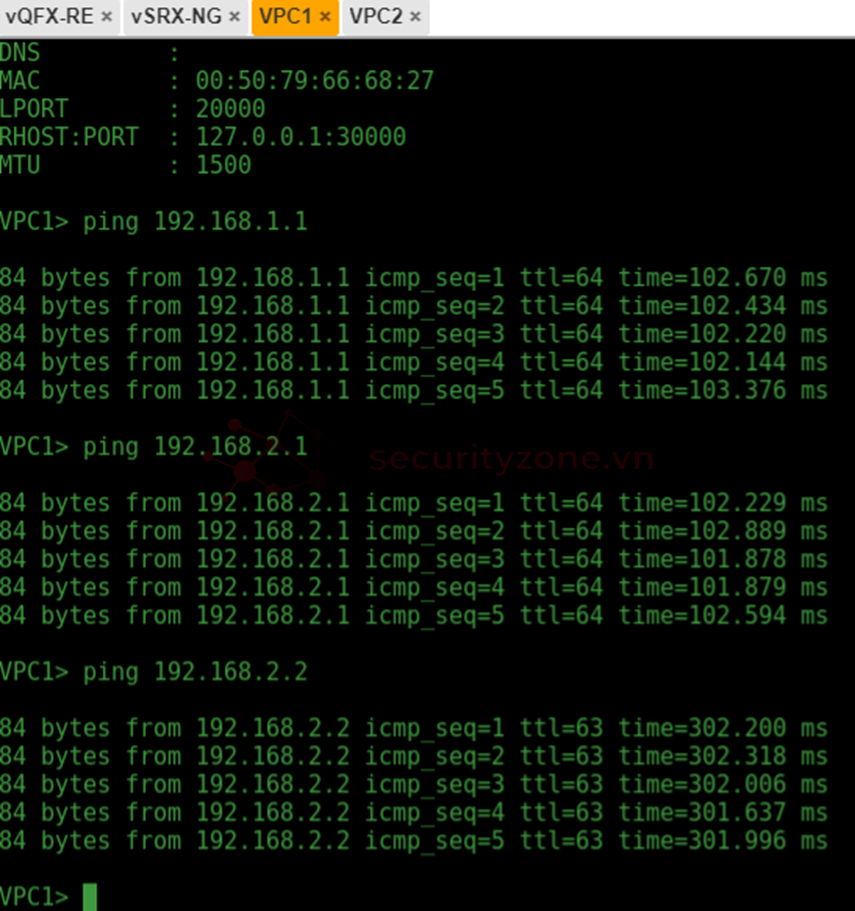
PC1 ping tới gateway, PC2
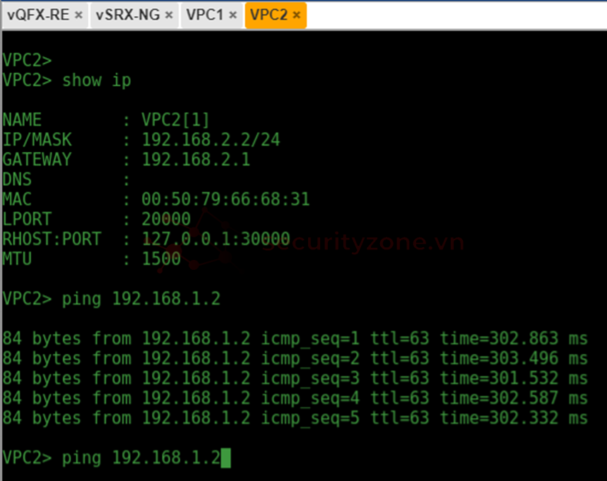
PC2 ping PC1
2.2 Layer 3 Switch Inter-VLAN Routing
Sơ đồ mô hình
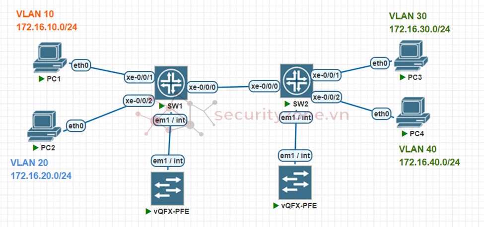
Ta sẽ cấu hình trước trên con SW1 và chọn nó làm Switch Layer 3
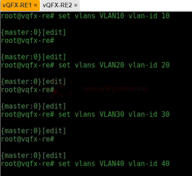
Đầu tiên ta tạo VLAN
set vlans VLAN10 vlan-id 10
set vlans VLAN20 vlan-id 20
set vlans VLAN30 vlan-id 30
set vlans VLAN40 vlan-id 40
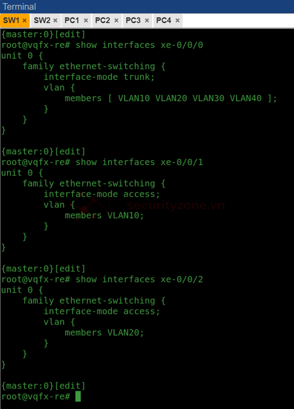
Sau đó ta tạo cổng trunk trên interface xe-0/0/0
set interfaces xe-0/0/0 unit 0 family ethernet-switching interface-mode trunk
set interfaces xe-0/0/0 unit 0 family ethernet-switching vlan member VLAN10
set interfaces xe-0/0/0 unit 0 family ethernet-switching vlan member VLAN20
set interfaces xe-0/0/0 unit 0 family ethernet-switching vlan member VLAN30
set interfaces xe-0/0/0 unit 0 family ethernet-switching vlan member VLAN40
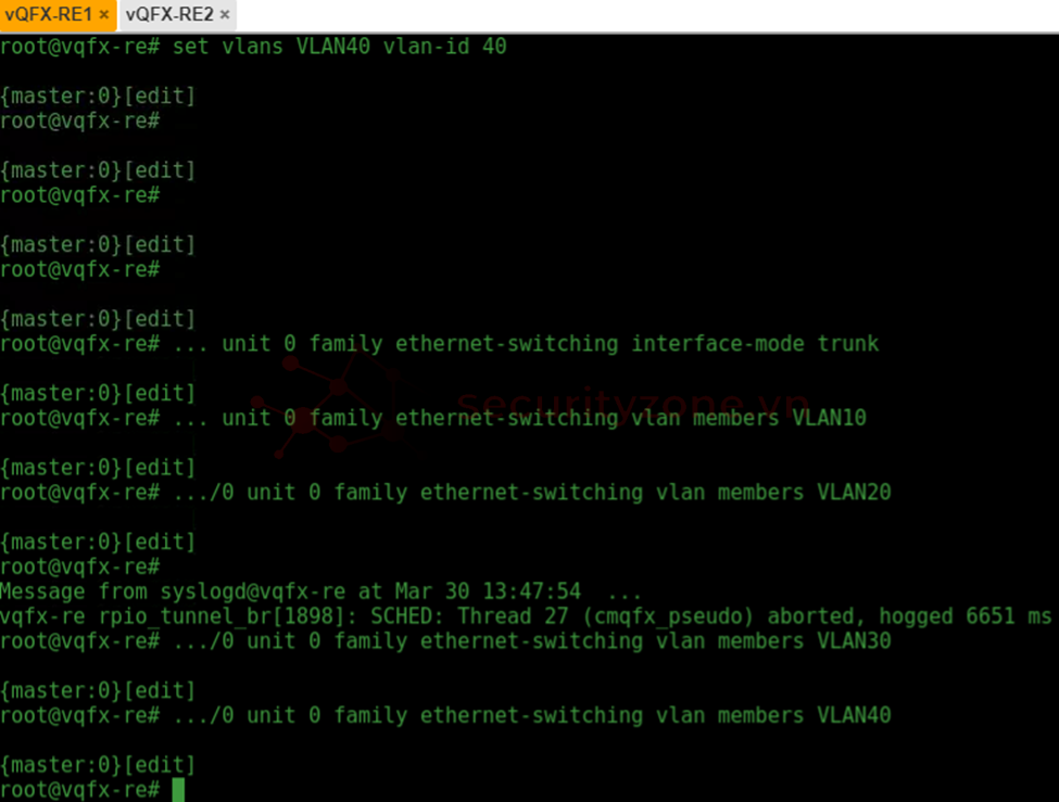
Các bước này làm tương tự với SW2
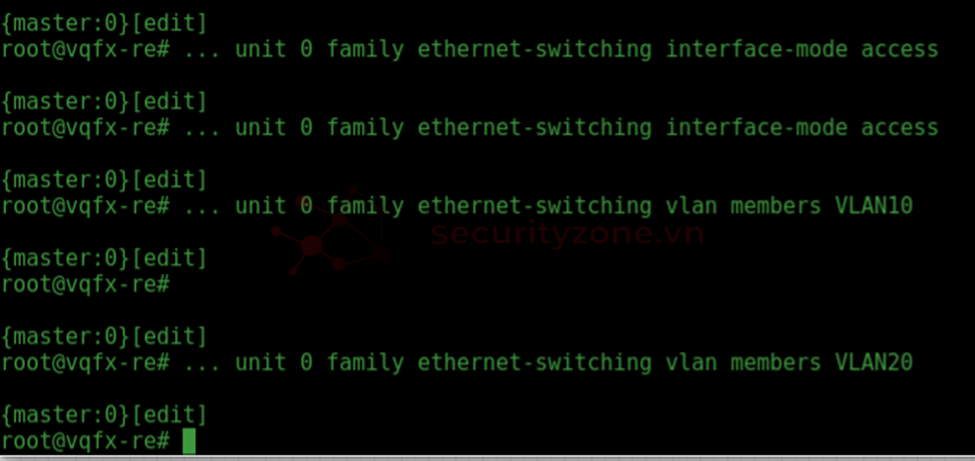
Tiếp theo ta tạo cổng access trên VLAN10 và VLAN20
set interfaces xe-0/0/1 unit 0 family ethernet-switching interface-mode access
set interfaces xe-0/0/2 unit 0 family ethernet-switching interface-mode access
set interfaces xe-0/0/1 unit 0 family ethernet-switching vlan members VLAN10
set interfaces xe-0/0/2 unit 0 family ethernet-switching vlan members VLAN20
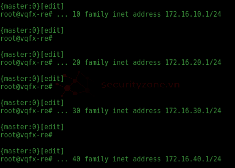
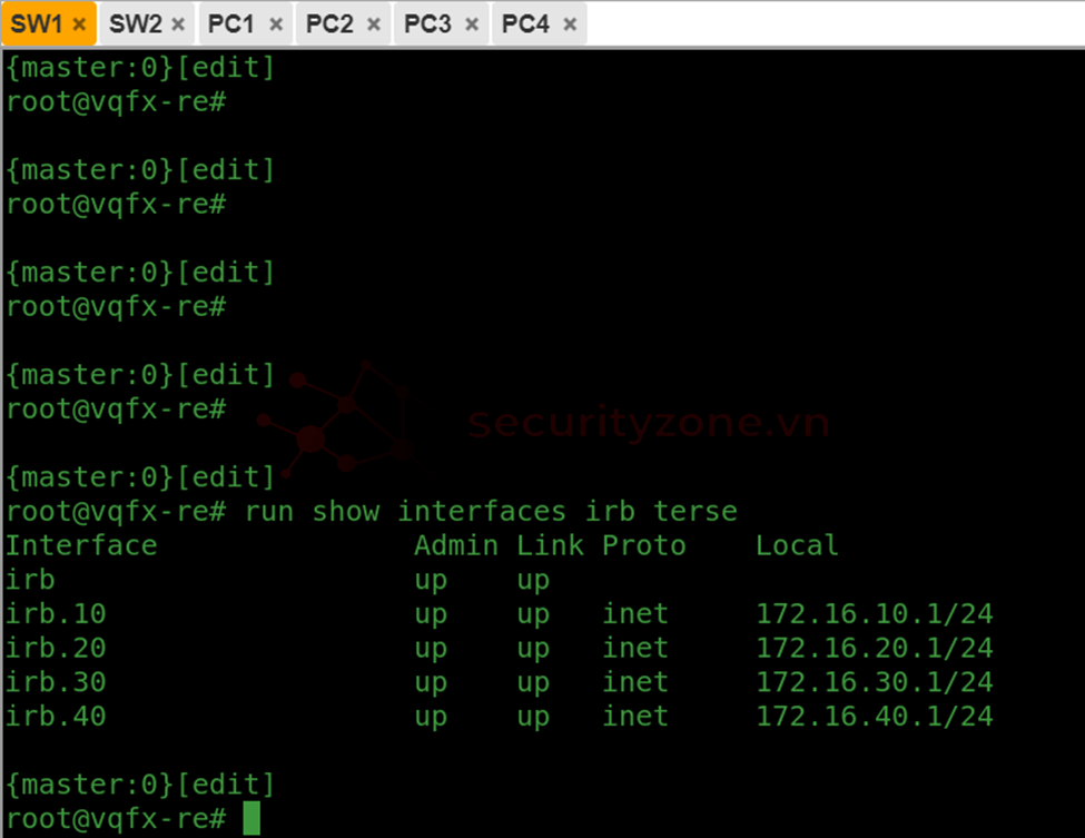
Ta tạo interface irb đại diện cho Switch Layer 3 trên thiết bị Juniper (irb viết tắt của Integrated Routing and Bridging - một loại interface logic được sử dụng để kết hợp chức năng routing (định tuyến) và bridging (chuyển tiếp lớp 2). ) và thêm địa chỉ ip cho mỗi interface được tạo
set interfaces irb unit 10 family inet address 172.16.10.1/24
set interfaces irb unit 20 family inet address 172.16.20.1/24
set interfaces irb unit 30 family inet address 172.16.30.1/24
set interfaces irb unit 40 family inet address 172.16.40.1/24
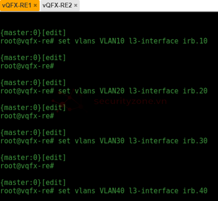
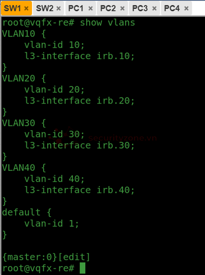
Add VLAN vào mỗi interface tương ứng
set vlans VLAN10 l3-interface irb.10
set vlans VLAN20 l3-interface irb.20
set vlans VLAN30 l3-interface irb.30
set vlans VLAN40 l3-interface irb.40
Ở thiết bị SW2 thì ta chỉ cần cấu hình thêm cổng access trên VLAN30 và VLAN40
set interfaces xe-0/0/1 unit 0 family ethernet-switching interface-mode access
set interfaces xe-0/0/2 unit 0 family ethernet-switching interface-mode access
set interfaces xe-0/0/1 unit 0 family ethernet-switching vlan members VLAN30
set interfaces xe-0/0/2 unit 0 family ethernet-switching vlan members VLAN40
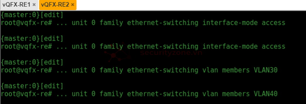
Kiểm tra kết quả
SW1
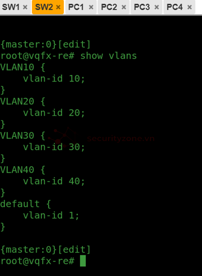
SW2
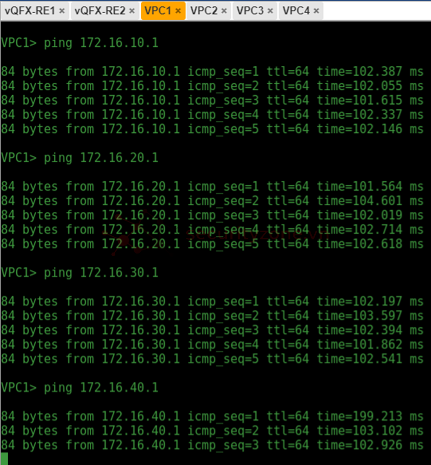
Ping thử từ PC1 về gateway PC1, PC2, PC3, PC4
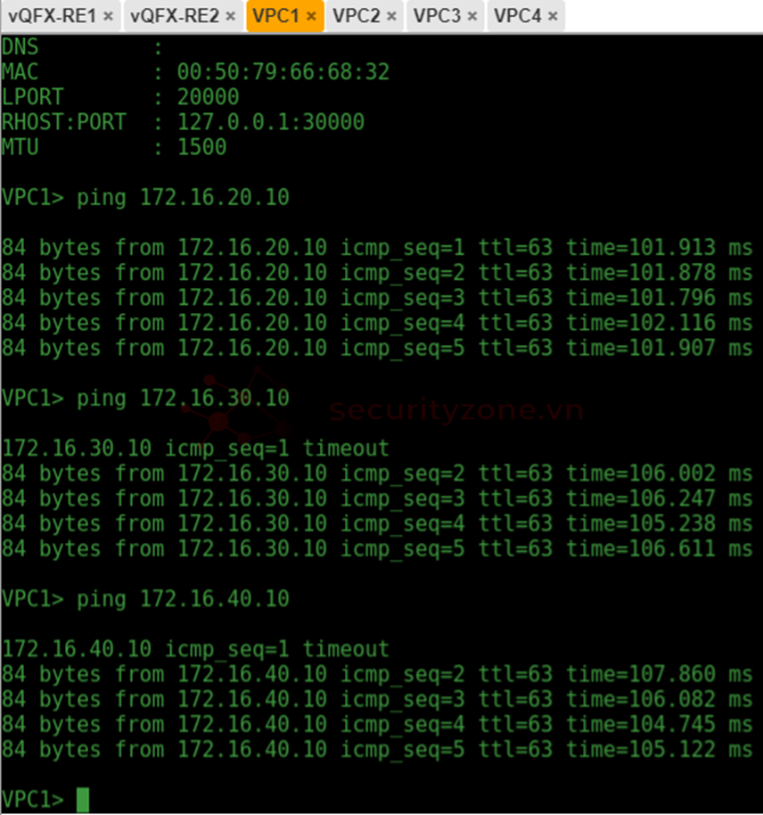
Ping thử PC1 qua PC2, PC3, PC4
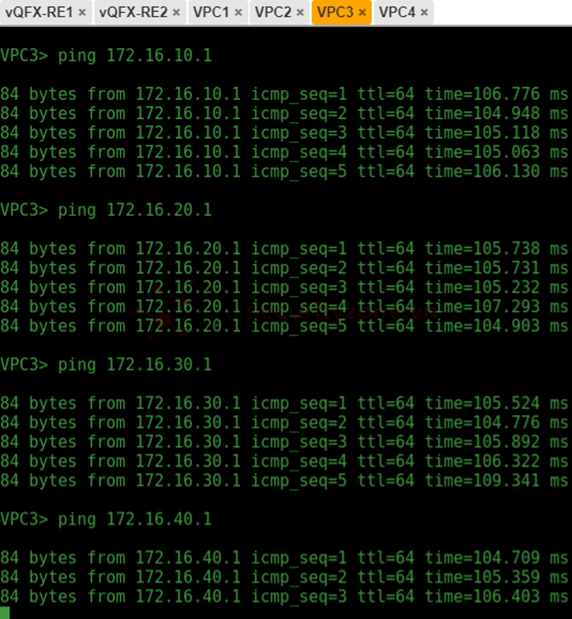
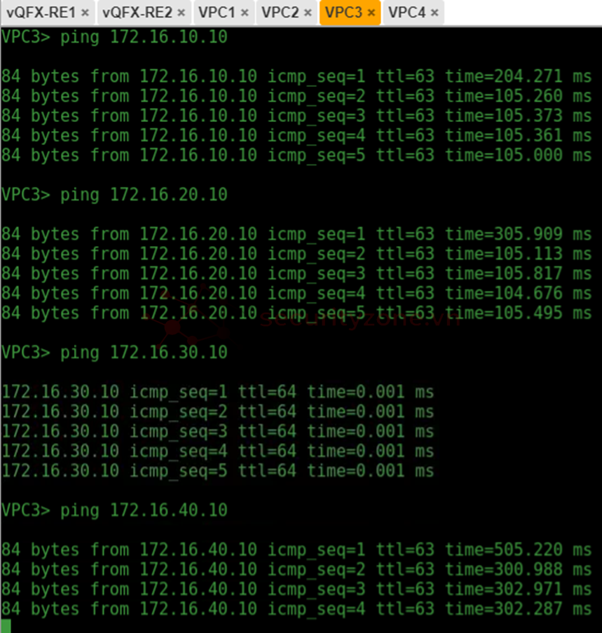
Ping từ PC3 về gateway, PC1,PC2, PC3, PC4
Ping từ PC3 qua PC1, PC2, PC4
Bài viết liên quan
Bài viết mới
